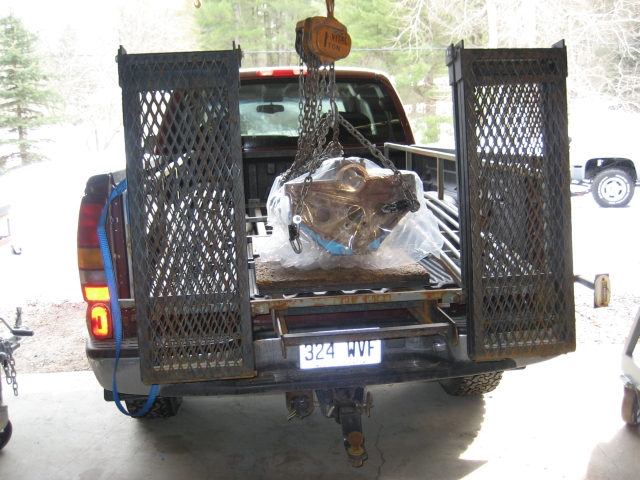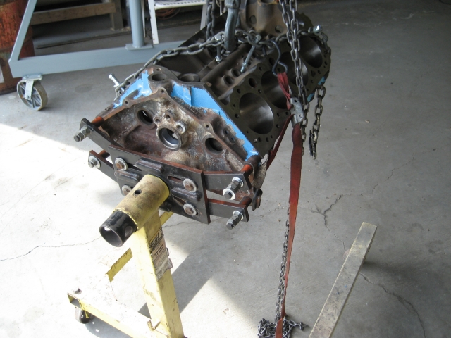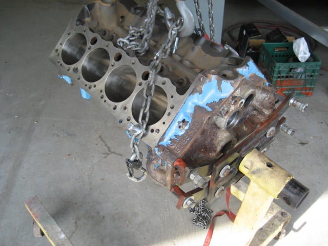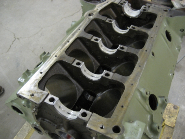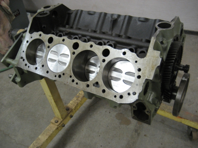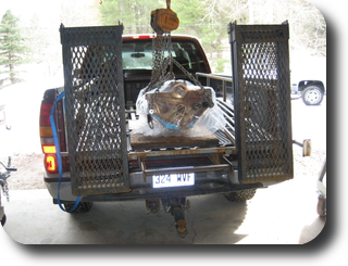
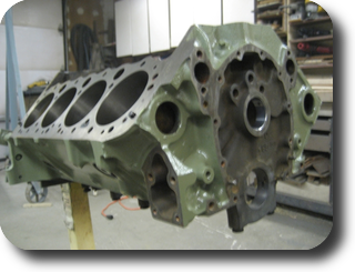
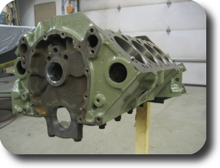
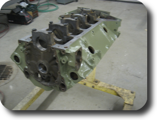
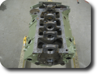
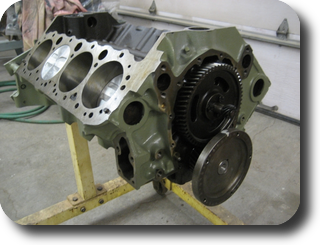
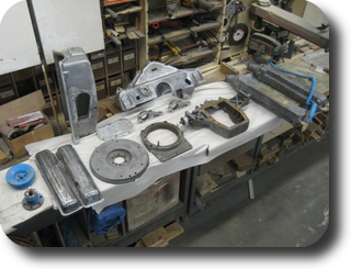
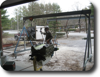
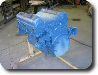
Back from the machine shop.
(06-MAR-2009)
|
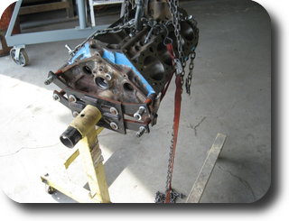
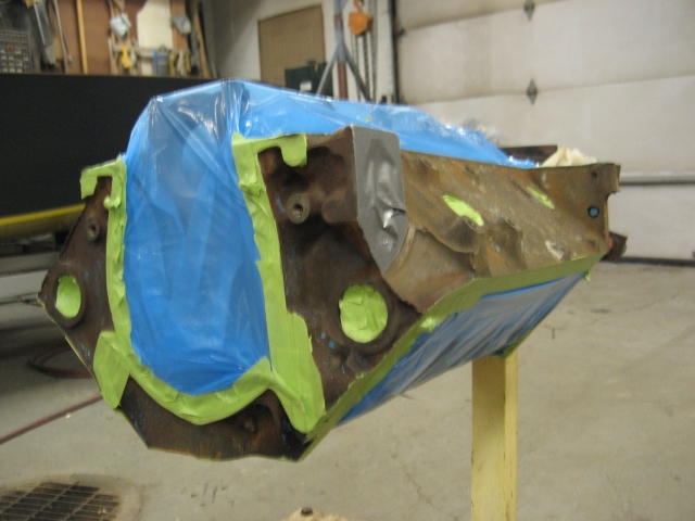
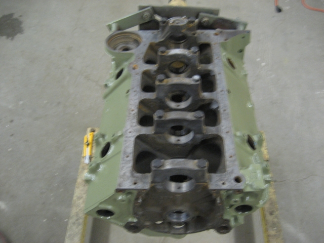
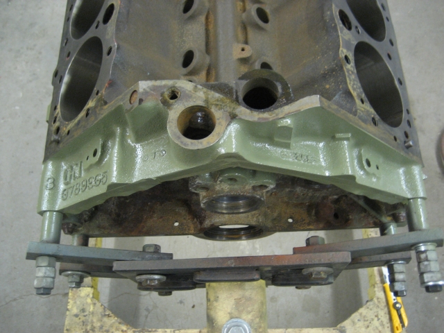
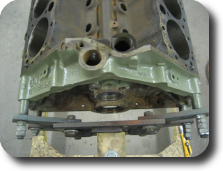
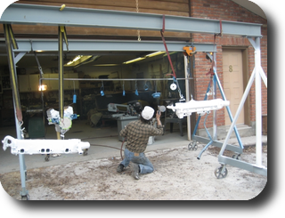
Prepping the block for paint. (07-MAR-2009)
|
|
|
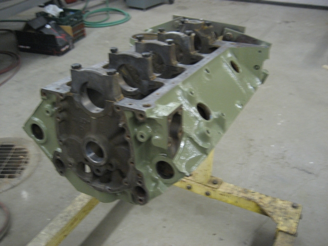
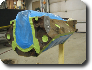
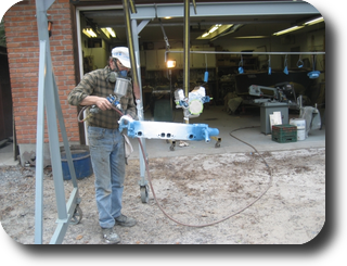
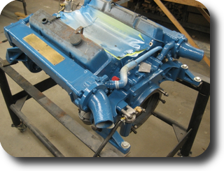
Block primed with DuPont 2580CR urethane primer.
(06-MAR-2009)
|
|
|
|
|
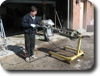
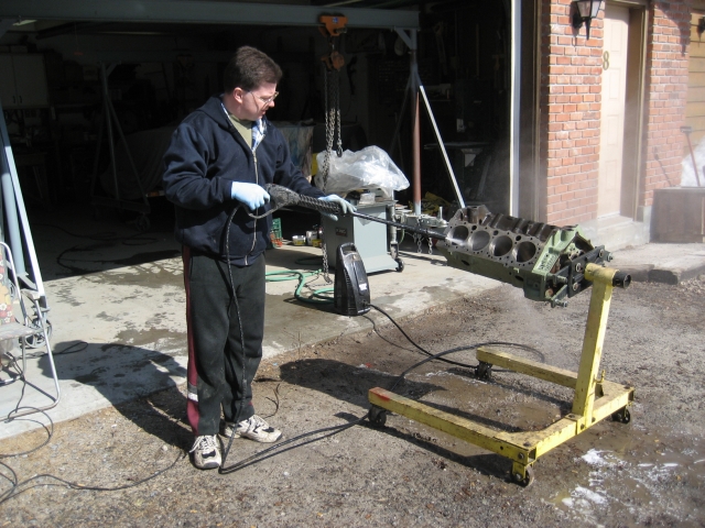
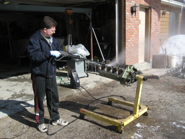
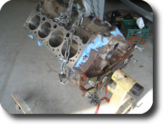
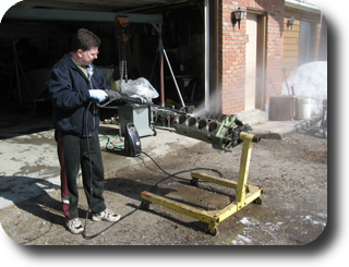
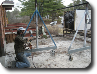
Pressure washing the engine block.(14-MAR-2009)
|
|
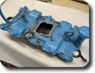
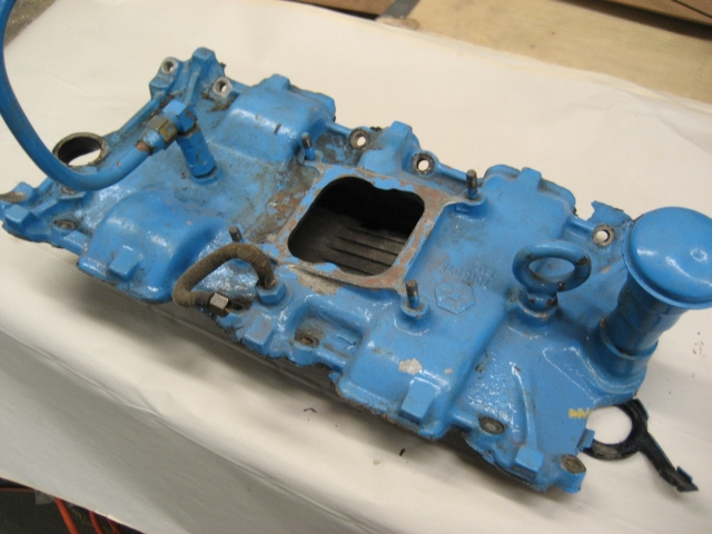
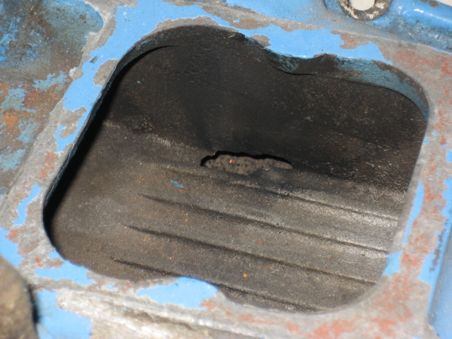
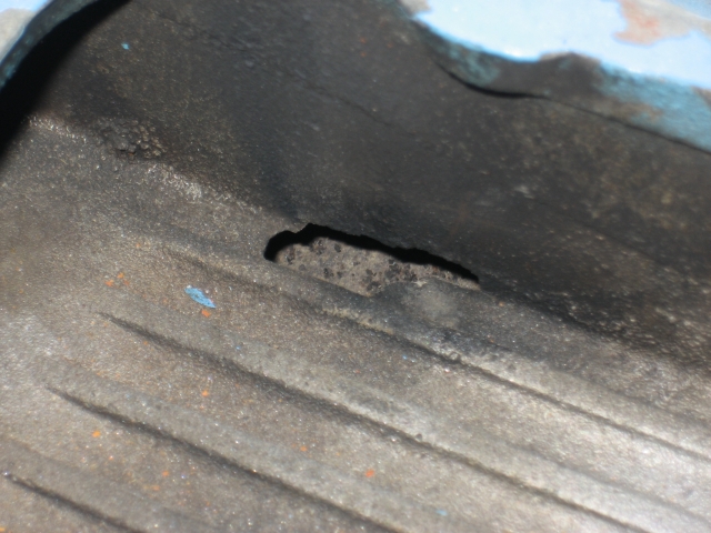
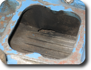
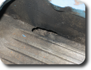
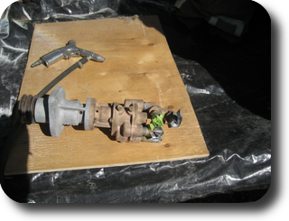
Intake manifold has a large hole in the bottom of the plenum. It will
have to be replaced.
|
|
|
(28-MAR-2009)
|
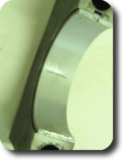
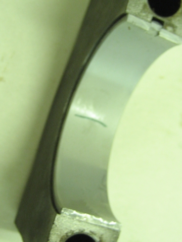
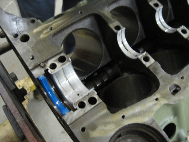
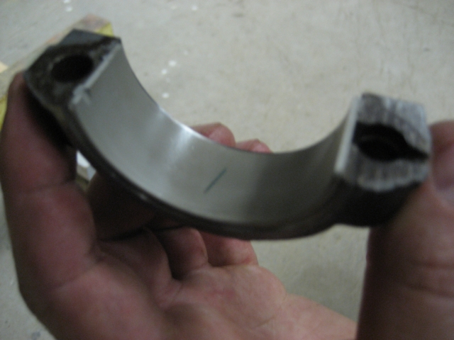
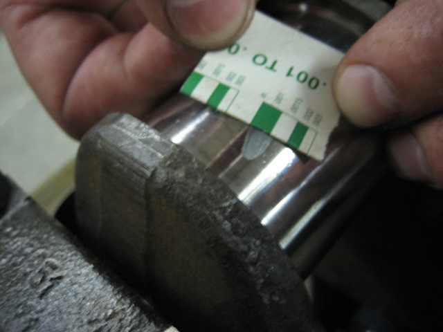
Cut and place a strip of plastigauge on a main bearing cap.
|
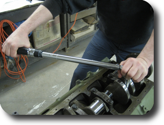
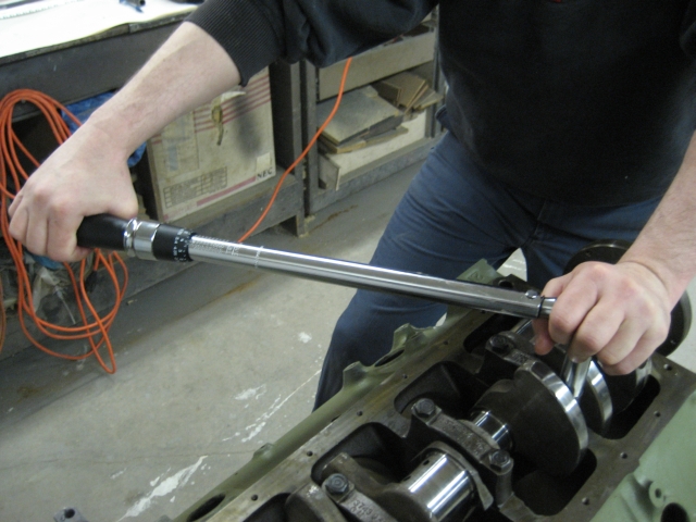
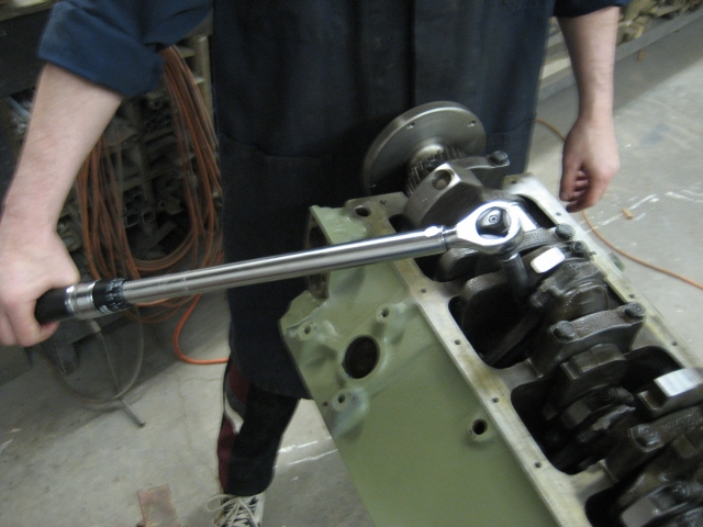
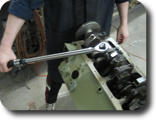
Torque the main bearing cap bolts to 65 ft/lbs.
|
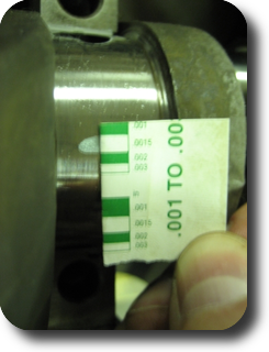
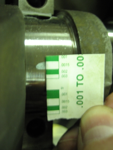
Determinine the clearance by matching up the compressed plastigauge strip with the
plastigauge kit's ruler. Crankshaft main bearing clearance : 001" - .004"
|
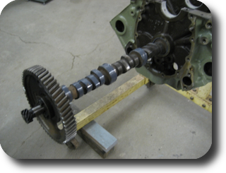
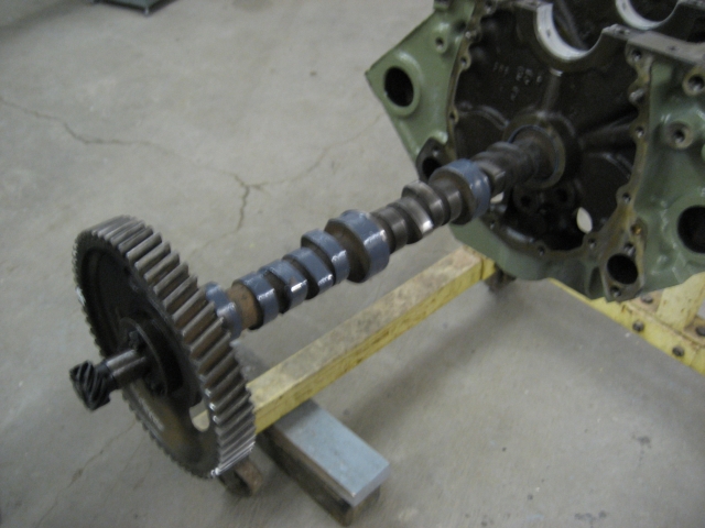
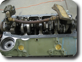
Coat the camshaft running surfaces with assembly lube and install it in the engine.
|
Install rear oil seal.
|
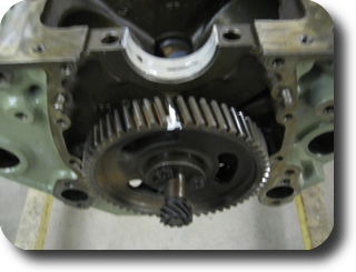
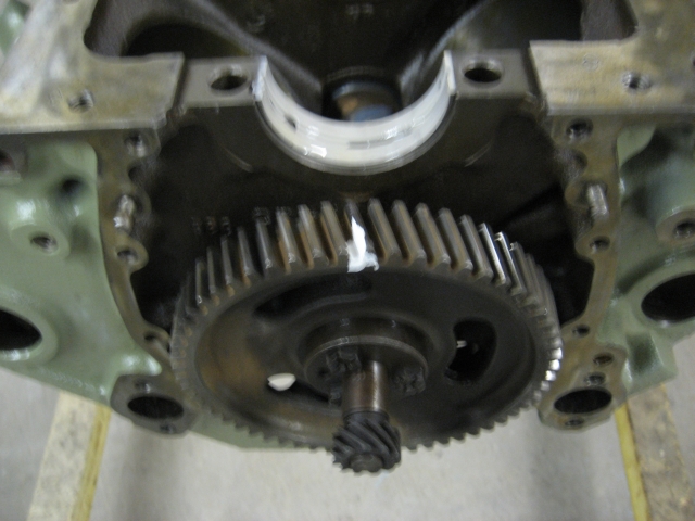
Locate the camshaft gear's timing mark and mark it with some Liquid Paper.
|
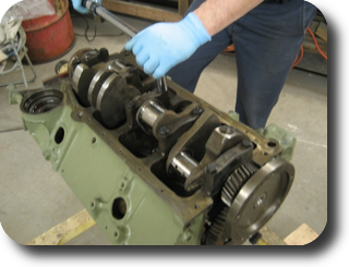
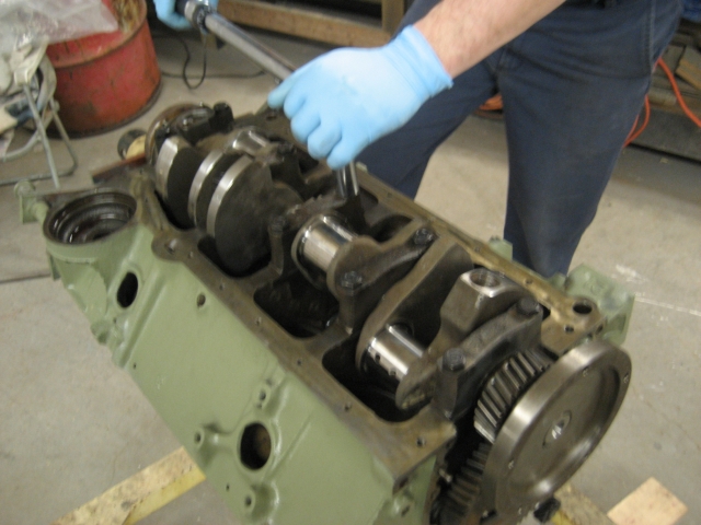
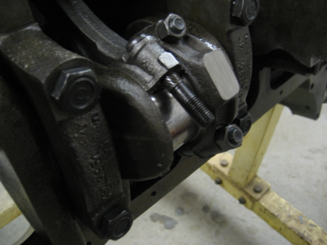
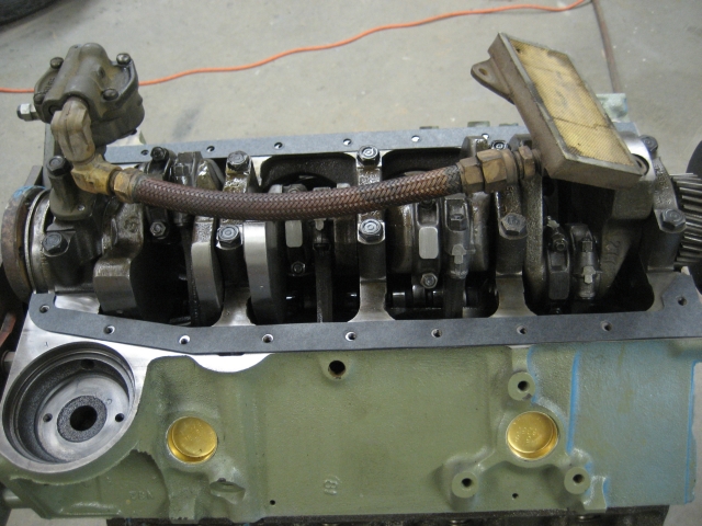
Install the crankshaft and main bearing caps. Ensure that the crankshaft and
camshaft timing marks are aligned properly.
|
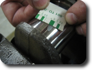
Measure piston ring gap. Reccommended clearances are usually included with the
piston ring set.
|
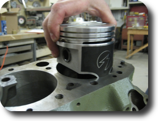
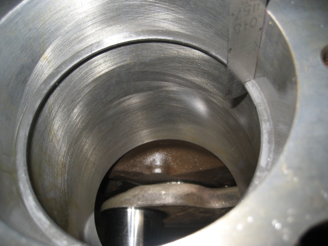
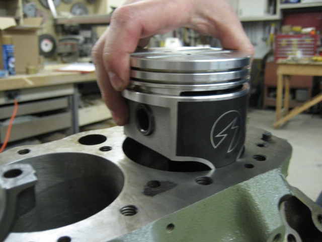
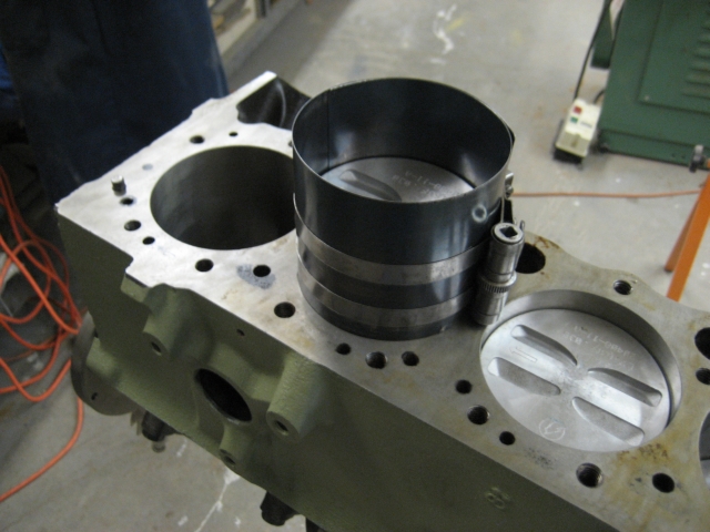
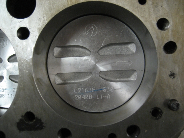
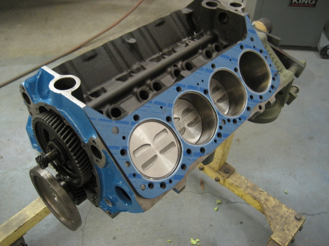
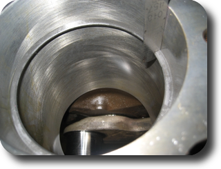
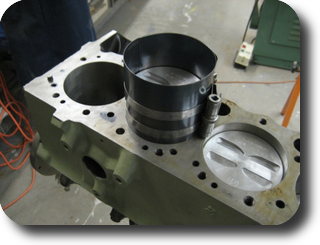
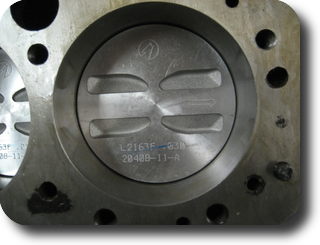
Install piston without rings to check bearing clearances. Stock cast pistons were upgraded to
forged units (.030" oversize).
|
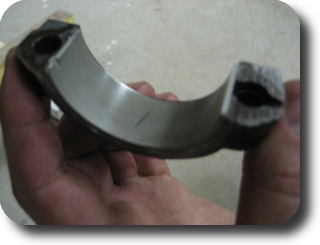
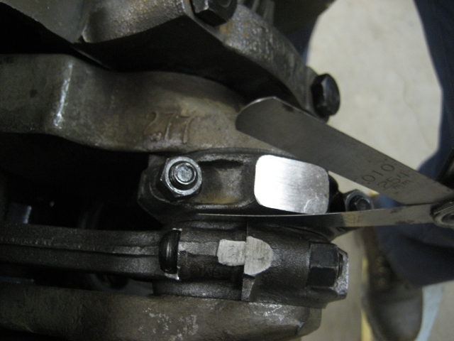
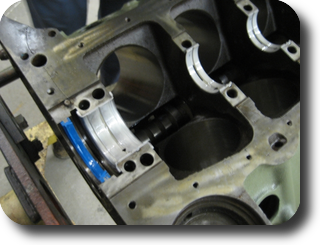
Cut and place a strip of plastigauge on the connecting rod cap bearing.
|
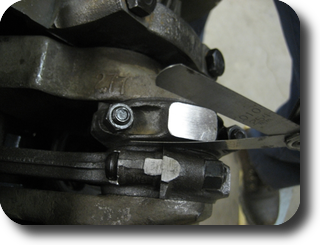
Torque the cap bolts and measure the connecting rod side clearance (two rods) : .008" - .014"
|
Connecting rod bearing clearance : .001"-.004"
|
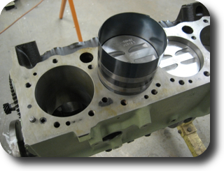
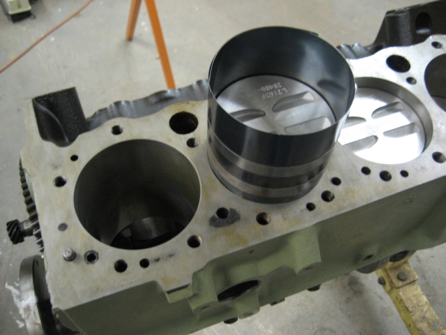
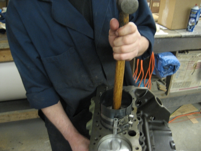
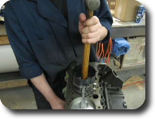
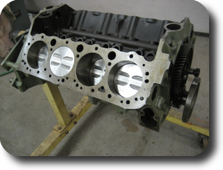
Installing the piston with a piston ring compressor. (03-APR-2009)
|
|
|
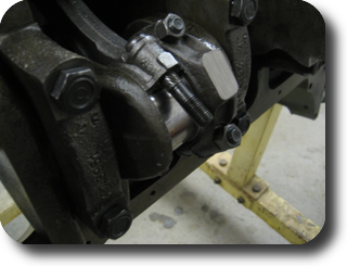
Installing the connecting rods.
|
|
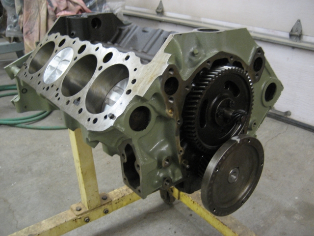
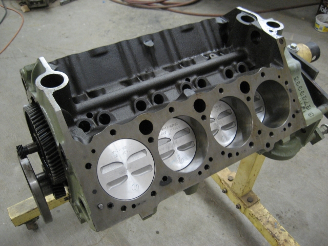
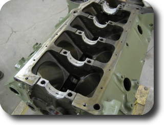
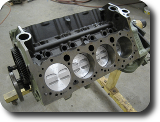
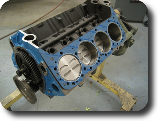
Short block completed.
|
|
|
|
| Engine Clearances |
Cyl | Main
bearing | Top
Ring |
Middle
Ring | Connecting
Rod | Rod Side
Clearance |
| 1 | .0015 | .017 | .017 | .001 | .009 |
| 2 | .002 | .017 | .016 | .001 |
| 3 | .0015 | .018 | .018 | .001 | .010 |
| 4 | .002 | .016 | .016 | .0015 |
| 5 | .003 | .017 | .018 | .001 | .010 |
| 6 | | .017 | .017 | .001 |
| 7 | | .018 | .016 | .0015 | .011 |
| 8 | | .017 | .017 | .0015 |
| Crankshaft end play | .003" |
|
| |
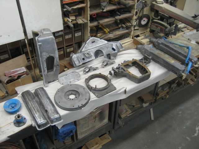
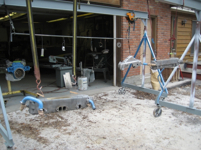
Exhaust manifolds and other painted parts were chemically stripped and sandblasted.
(09-APR-2009)
|
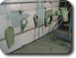
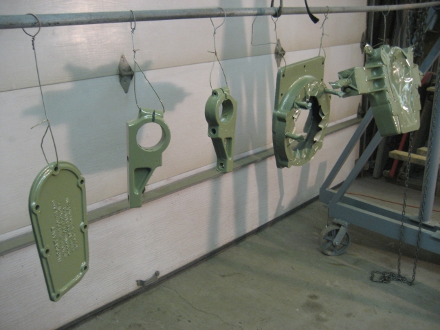
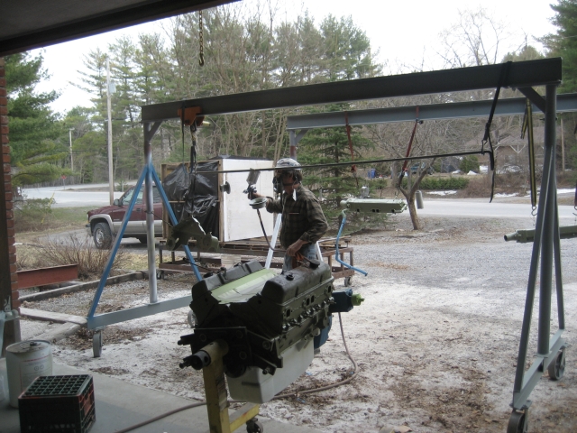
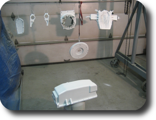
Parts were primed with DuPont 2580CR DTM urethane primer.
(10-APR-2009)
|
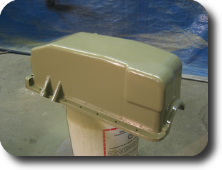
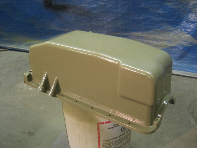
Aluminum oil pan was etched with DuPont Metal Conditioner prior to priming. This
promotes paint adhesion on bare aluminum parts.
|
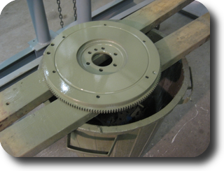
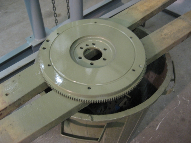
Flywheel.
|
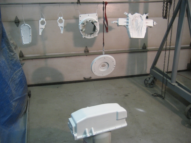
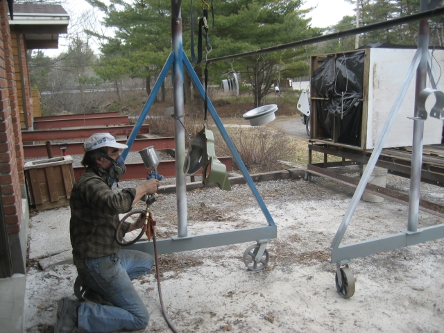
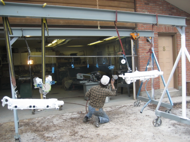
To stabilize the color and kick up the topcoat, we sprayed a white basecoat. Paint
is DuPont Imron urethane.
|
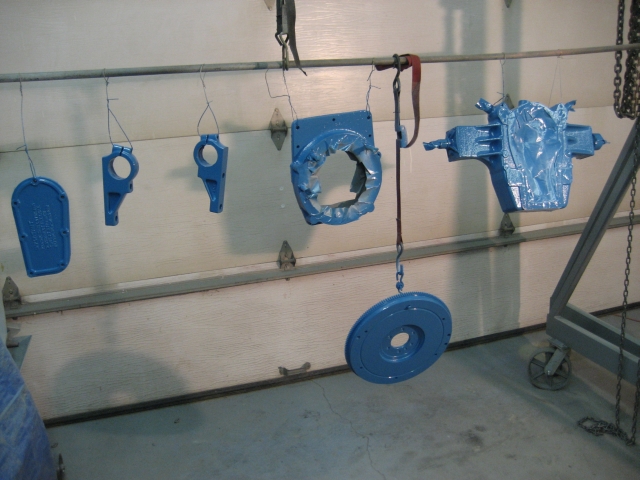
We couldn't get an Imron color match to the Chris-Craft blue, so we used a
Nason acrylic enamel which was custom mixed using DuPont's Kodak color match system.
|
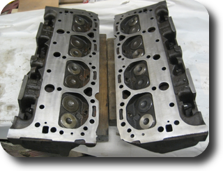
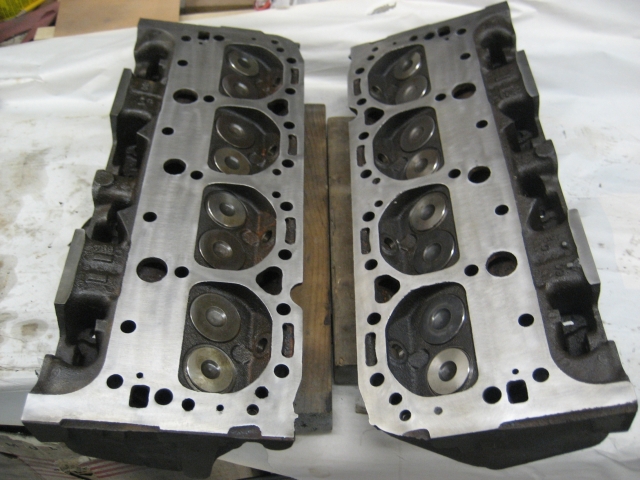
Rebuilt heads. New valves, valve guides and valve seats.
(11-APR-2009)
|
Marine head gasket.
|
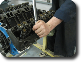
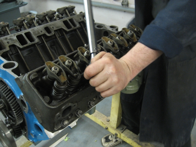
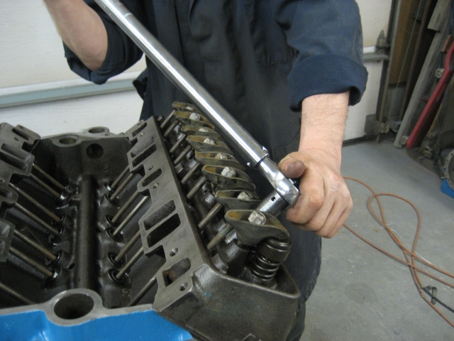
Cylinder heads torqued to 65 ft/lbs.
|
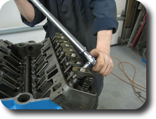
We completed the valve train by replacing the old solid lifters with a Comp Cams solid
lifter kit. The original pushrods and rocker arms were in good shape so they were
cleaned and reused.
|
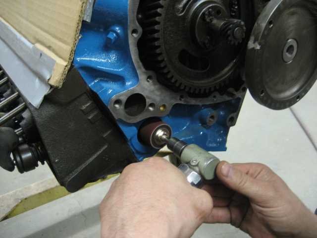
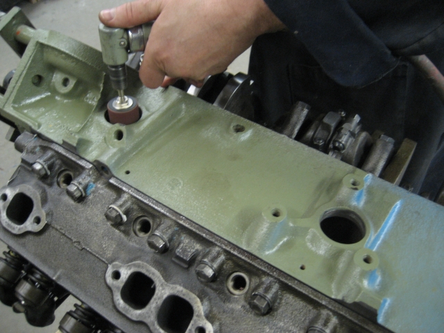
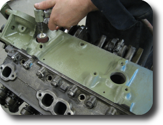
Frost plug holes were scuffed to bare metal.
(13-APR-2009)
|
|
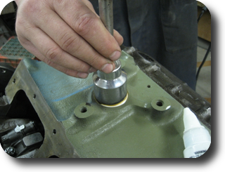
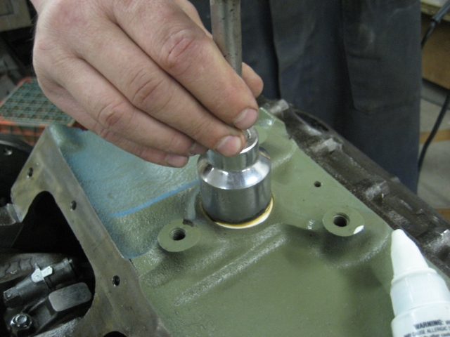
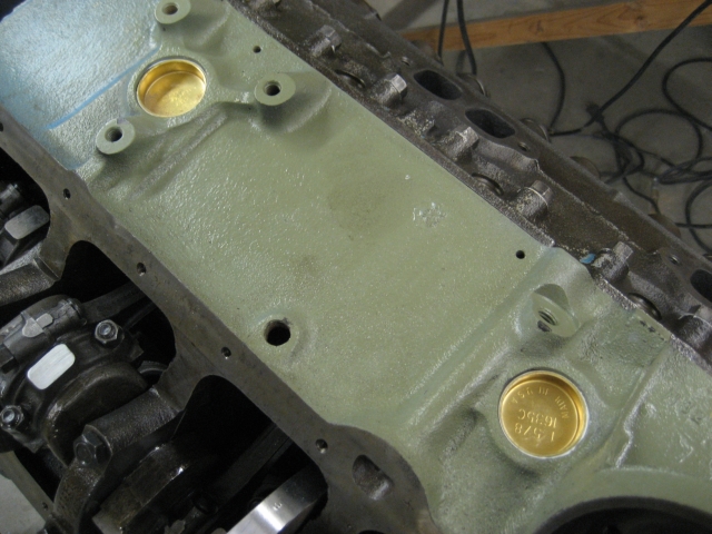
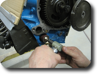
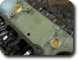
Brass frost plugs installed with a socket used as a drift.
|
|
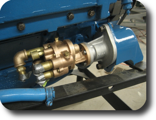
Oil pump, pickup hose and pickup screen assembly installed.
|
Oil pan installed. We prepainted the block's front face because it will be
partially obstructed when the rear cover is installed.
|
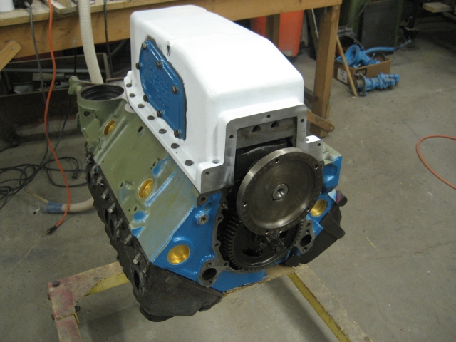
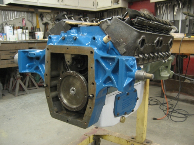
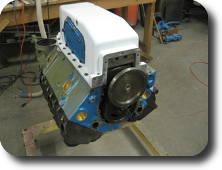
Rear cover installed.
|
As soon as the engine is buttoned up, the cylinder heads will be primed, remaining
non-blue parts will be painted white and then topcoated with blue paint.
|
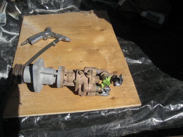
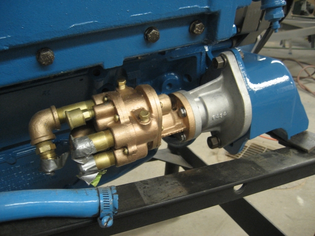
Water pump bead blasted. (17-APR-2009)
|
Bare sandblasted/bead blasted parts.
|
Parts primed with DuPont 2580CR DTM urethane primer.
|
Base coat of white Imron urethane.
|
|
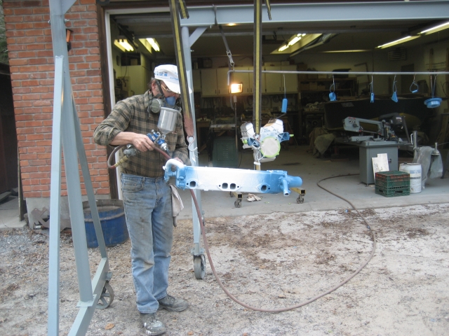
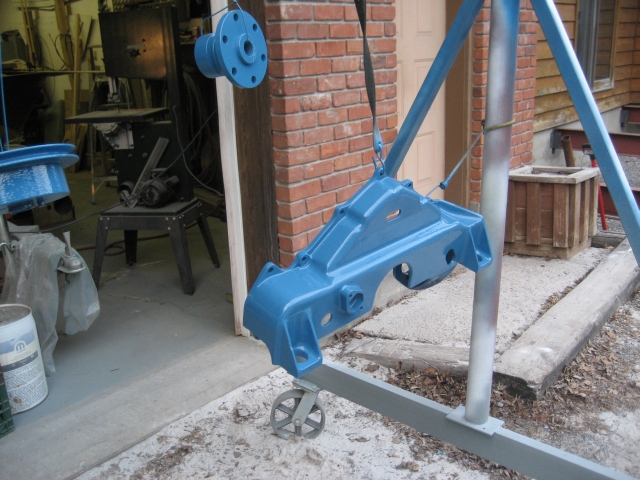
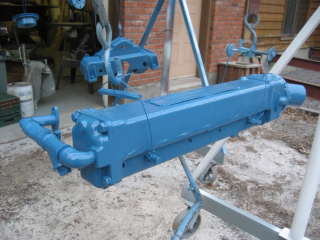
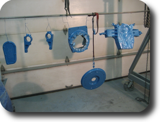
Nason acrylic enamel custom mixed to match Chris-Craft Blue.
|
|
|
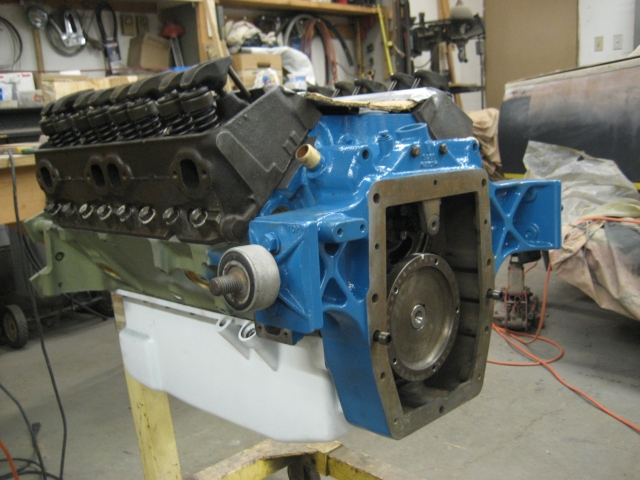
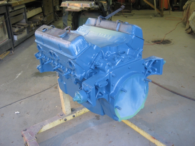
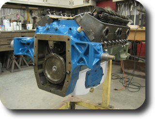
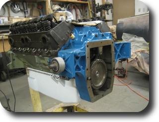
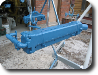
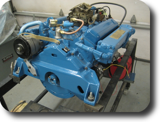
Engine block painted.
|
Assembly begins. (22-APR-2009)
|
|
|
|
Water pump sprayed with Nason Urethane Clear to protect the raw aluminium and bronze parts.
|
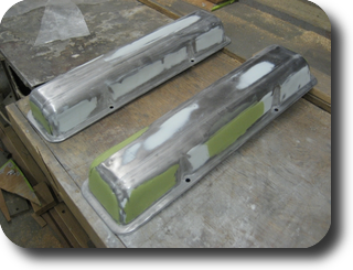
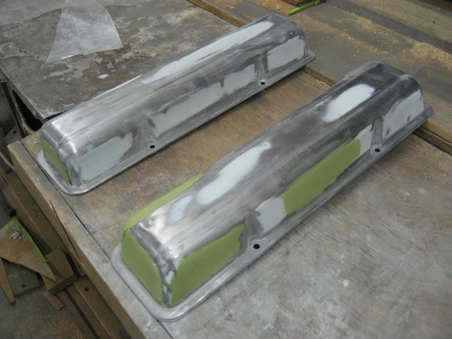
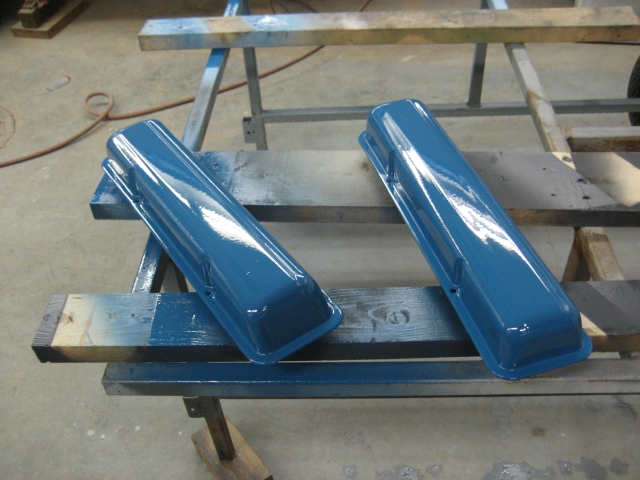
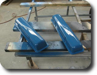
Polyester body filler applied to the valve covers.
|
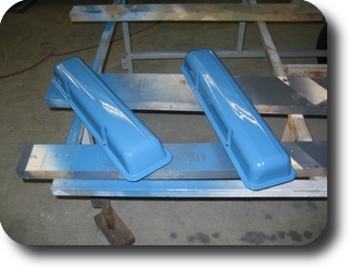
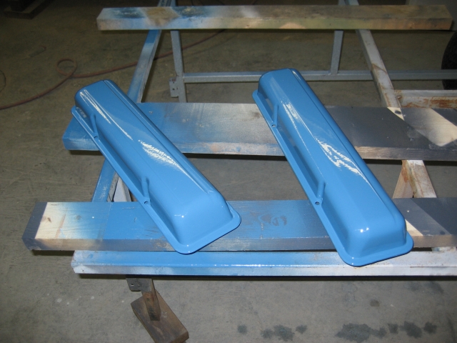
Primed, base-coated white Imron and topcoated with blue acrylic enamel.
|
|
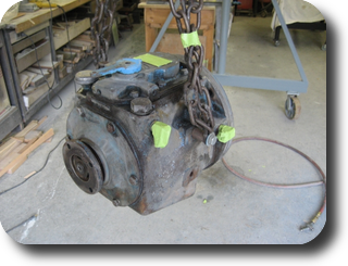
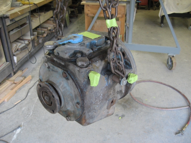
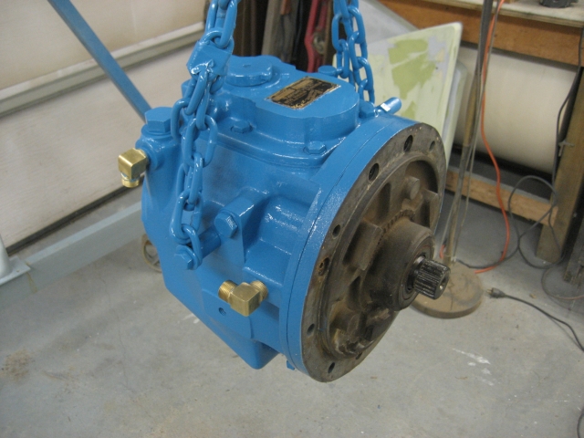
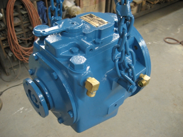
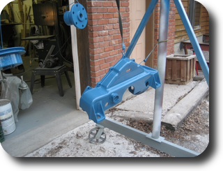
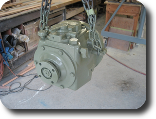
Paragon HF7 transmission bead-blasted and chemically stripped.
|
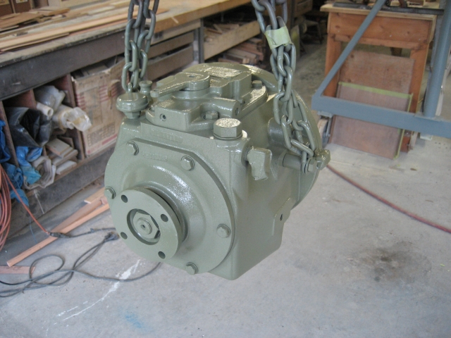
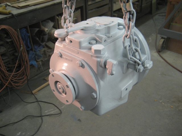
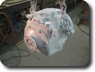
Primed.
|
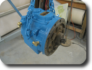
Base-coated.
|
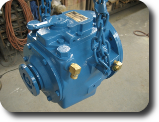
Top coated.
|
|
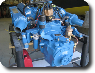
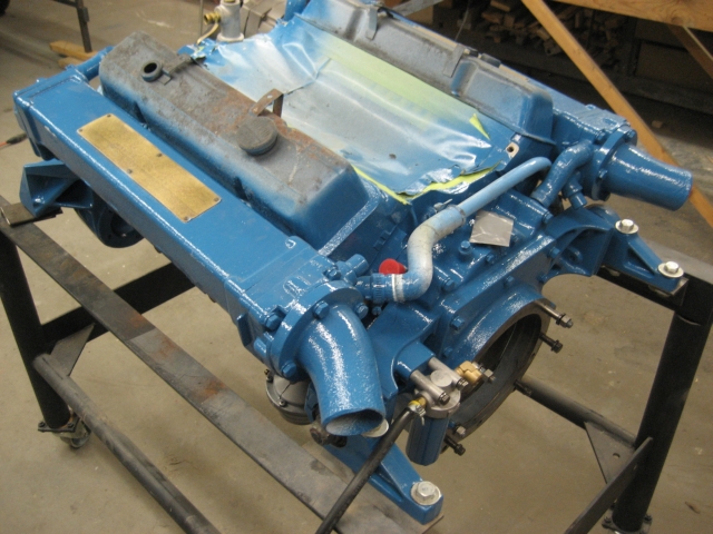
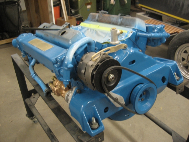
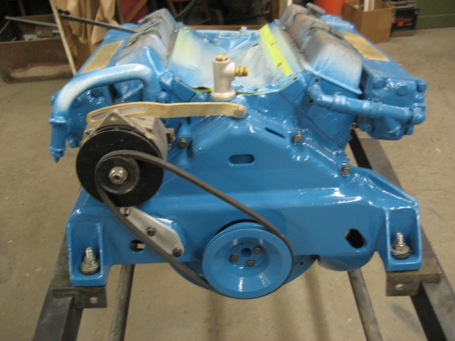
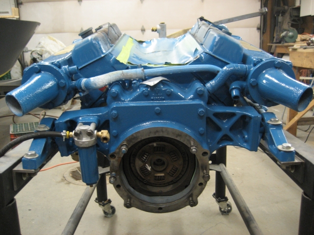
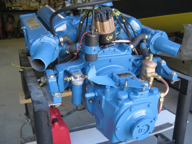
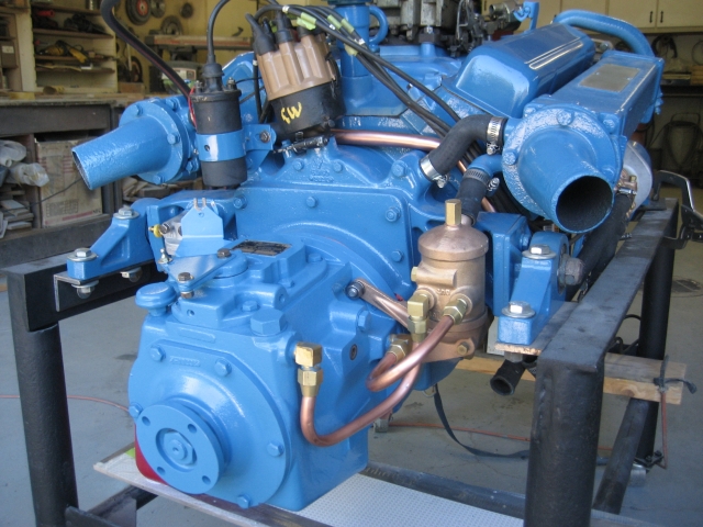
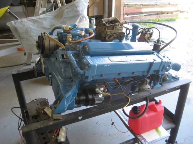
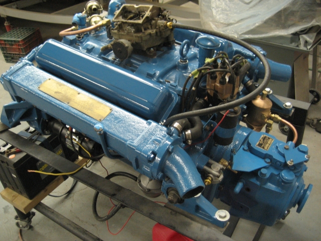
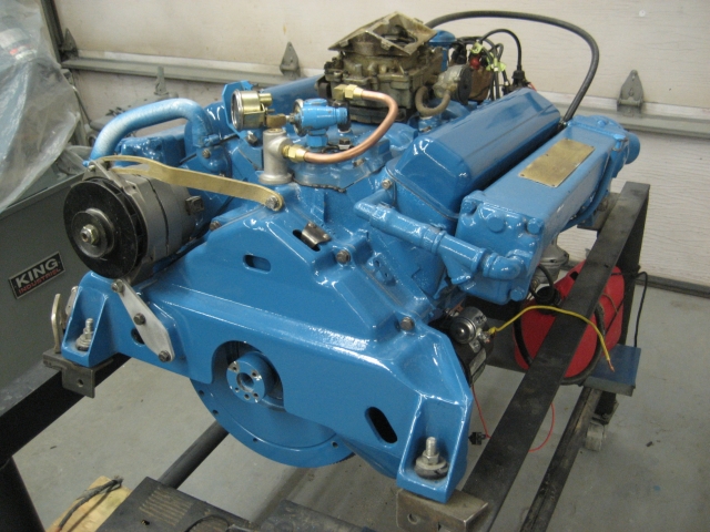
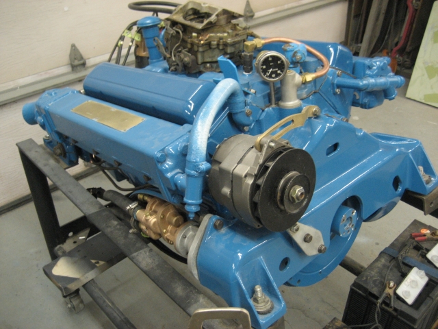
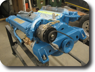
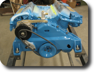
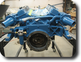
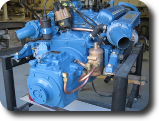
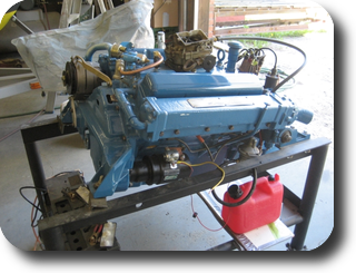
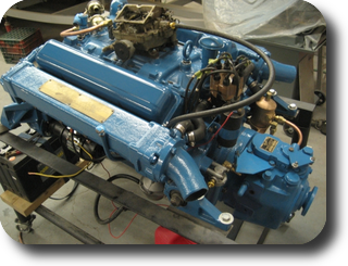
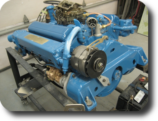
Mounted on the engine run stand and re-assembled.
|
|
|
|
|
|